
Instructor:
Dan Beert
ASSIGNMENT #6: Building
Sections & exterior elevations
Building Section
1. Media: lead on vellum titleblock
sheets. One section drawing will be drawn at 1/4”=1’-0” scale. Find the section
symbol on the floorplan handouts for section 1/A3.2. This corresponds with the
section view on your handout that you will draw. This assignment requires information
from the floor plans and handouts.
2. You will measure the handouts at 1/8”
scale to the nearest 1” increment.
3. Because
this is a DESIGN section, and not a CONSTRUCTION section (see Ching pp. 36,
55-63). Therefore, the construction details seen in the handout’s section
drawing will not be shown.
4. In a design section, things like the juncture of the foundation, the
floor structure, and the wall will only be profiled: Items cut in
section will appear darker than those beyond. A design section focuses on the
volume of interior space and the shape and openings of the interior/exterior
enclosure.
5.
EXTERIOR
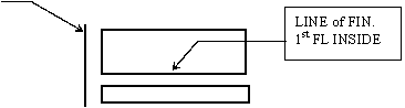
The finished floor lines for each floor
shall be shown on the drawing by using an elevation datum symbol. Included with each is the floor name, and elevation
relative to the first floor line (which is referenced as 0'-0"). (See notes
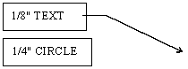
on p. 3) EXAMPLE: The 1st Floor elevation datum symbol aligns with
the finished floor and will appear (something) like this (see linetype handout:
centerline style):


6. The roof pitch shall be indicated (See
notes on p. 3). Dimension the width of roof overhang. Find the most detailed drawing of the overhang. Use this dimension.
7. Show all footings in the section view. Rafters, joists, and insulation will
not be shown in the section view, since it is a design section. However, you
will show the roof truss seen in this
section view.
8. Room names and numbers are typically
indicated in rooms on the building sections. Place these so they do not
obstruct any more than necessary.
9. The section shall be titled using
standard drawing title conventions (See p. 3).
10. Draw building section cut symbol on the original vellum floor plans as
shown on the originals, and add numbers: 1 / A4: 1 goes above, A4 in bottom of
circle.
Exterior
Elevations
1.
Two exterior
elevations will be drawn at 1/4”=1’-0”. One on the same sheet as the section
view, and the other on a separate sheet. The South Elevation corresponds with
Section AA (1/A4) and will be drawn alongside it on the same sheet (Sheet A4).
The West Elevation will be drawn on its own sheet (Sheet A3).
2.
Arrange Sheet
A4 so that the South Elevation is to the right of the section view. Place the drawings so that the floor lines
align with each other and so that there will be adequate space between the
drawings to allow for notes and dimensions (see page 3 of handout). Balance the
drawings on the sheet so that there is more space below the drawings than above
them. This is because the drawing titles will be placed below, and there may be
additional notes below, as well.
3.
Arrange the
West Elevation on Sheet A3 so that it is in the same approximate vertical location
on the sheet as the drawings on Sheet A4.
4.
Several line
types will be used to produce the elevation drawings. Thick profile lines for
the outline of the elevation and grade (ground) line, and thin, crisp lines for entourage: representation of specific
materials (i.e. the roofing material, wood siding, etc.). Refer to the Ching
and Yee books for examples of how to draw convincing representations of
building materials.
5.
Roof material
and overhang profiles should correspond with the most detailed information contained in the handouts. Typically, the
most detailed views are drawn after
the overall views because that is when the actual construction methods are
decided on. This means that some information in the handouts may be different
than what’s shown on the elevation views.
6.
Door and
window locations and widths should correspond to your floor plan and sections. Show door
and window heights as indicated in
the section/elevation handouts.
7.
Entourage for
the exterior wood sheathing should be on the back of the vellum. Render glazing
(glass) as a tone pattern using lines
(suggestions: Ching pp. 132, 142, 170), also on the back of the vellum.
8.
The foundation
is hidden below grade, and should
be represented by long dashed lines. The foundation should be drawn solid where
it is exposed.
9.
The height
dimensions and finished floor lines for each floor shall be shown on the elevation
drawings by using datum symbols and alternating a (thin) long dashed line with
a short dashed line, similar to note 5, page 1. Each line shall be titled.
(i.e. “First Finish Floor Level” at 1/8” text height.)
10.
Include the
notes listed on the following pages. All notes shall be aligned vertically on
the sheet, flush left, at either side of the elevation. Use suggested note
locations from drawings that will be posted in the studio.
11.
All drawings
shall be titled. Use the compass direction to label the elevations. (For
example “South Elevation.”) Use standard drawing title conventions.
REVIEW PINUP:
DUE:
Annotation
Find these notes on the handouts and
place them on your drawings in an appropriate location. It may be that you can
find a better location for them than what is shown on the handouts, or that you
will require more (or less) lines of text to write the same note. NOTE: Some
notes have been excluded.
In capital letters, below, are the
notes; in parentheses and italics, notes and comments on location, etc.
Section AA
(place
the number 1 in the drawing label circle and use the drawing title: SECTION AA)
- Elevation
Datum Symbols
(Arrange so that they are between and shared by Section AA and South Elevation.)
FIRST FLOOR +0’-0”
SECOND FLOOR +10’-0”
T.O. PLATE +20’-0” (top of plate is top of whale bone elements)
RIDGE +28’-0”
T.O. CHIMNEY +30’-0” (top of chimney)
(These should be arranged so that they are between and shared by two adjacent drawings.)  Roof
Slope Symbol
1/8” text height
Overall:
symbol is no longer than 1”
Notes:
- 1X6 CLR. CEDAR T&G CEILING
- (2) 4X10
BEAMS BOLTED TO WHALE BONES & SHAPED 4X12 SPLICE @ CENTER
- AWNING
(N.I.C.)
- COPPER
CAP
- 6X12
ROUGH HEWN MAPLE MANTEL
- DRYGROUT STACKED BASALT FIELDSTONE VENEER OVER 2X
FRAMING (on Sect. CC @ top of chimney; find similar location)
- SHAPED COPPER CAP (on Sect. CC @ top of chimney; find
similar location)
- Add room names AND room numbers as on plans.
Drawing Titles
- Label as: Section AA. Change scale to read
exactly: SCALE: 1/4"=1’-0”
- Always number according to order on the page: left to
right, then top to bottom.
South Elevation
Notes may
appear on other elevations. Find best corresponding location on this elevation.
- HORIZ. 1X4 CEDAR T&G SIDING
- PAINTED WOOD FASCIA W/PAINTED MTL. GUTTERS
- STAINED WOOD BEAMS
- 1X12 CEDAR ACCENT BAND (TIGHT KNOT) TRANSLUCENT STAIN
- HORIZ. LAPPED COPPER SIDING
- VERT. 1X4 TIGHT KNOT CEDAR TONGUE & GROOVE SIDING
W/ TRANSLUCENT STAIN
- VINYL WINDOW SYSTEM
- WOOD & METAL AWNING (N.I.C.) (note appears at bottom of drawing)
- DRYGROUT STACKED BASALT FIELDSTONE VENEER OVER 2X
FRAMED BOX
In
capital letters, below, are the notes; below them, the elements that are
referenced in the notes.
West Elevation
- ASPHALT COMPOSITION SHINGLE (this appears on the EAST
elevation; place here instead)
- COPPER SIDING
- LAPPED COPPER AT RECESS
at reveal on face of NOOK enclosure - STAINED WOOD BEAMS
projections at top of chimney - HORIZ. LAPPED COPPER SIDING
chimney finish - METAL & WOOD AWNING (N.I.C.)
suspended over French doors - COPPER CAP
top of stone fireplace surround - DRY GROUT STACKED BASALT FIELDSTONE VENEER OVER 2X
FRAMED BOX
fireplace surround